Čo je to betónová doska s dutým jadrom a prečo je to dôležité v modernej výstavbe
A dutá betónová doska je prefabrikovaný predpätý betónový prvok s pozdĺžnymi dutinami – zvyčajne kruhovými alebo oválnymi – prechádzajúcimi po jeho dĺžke. Tieto dutiny znižujú celkovú hmotnosť dosky až o 40–50 % v porovnaní s pevnou betónovou doskou ekvivalentných rozmerov, pričom zachovávajú vynikajúce konštrukčné vlastnosti v ohybe, šmyku a požiarnej odolnosti. Táto kombinácia robí z dutých dosiek jeden z najpoužívanejších podlahových systémov v komerčných budovách, viacposchodových obytných blokoch, parkoviskách, priemyselných skladoch a infraštruktúrnych projektoch na celom svete.
Základný záver je jednoduchý: betónové dosky s dutým jadrom poskytujú vynikajúci pomer pevnosti k hmotnosti, rýchlu montážnu rýchlosť a zníženú spotrebu materiálu. Pri výrobe v moderných prefabrikátoch – kde presné debnenie, debniace magnety a automatizované lejacie lôžka definujú kvalitu výroby – tieto dosky dôsledne spĺňajú prísne rozmerové tolerancie a náročné konštrukčné špecifikácie. Pochopenie spôsobu ich výroby, manipulácie a inštalácie je nevyhnutné pre inžinierov, dodávateľov a profesionálov v oblasti obstarávania, ktorí hľadajú nákladovo efektívne a vysokovýkonné podlahové riešenia.
Ako sa vyrábajú betónové dosky s dutým jadrom
Výroba dutinkových betónových dosiek prebieha takmer výlučne v prefabrikátoch, pričom sa používa jedna z dvoch dominantných metód: proces extrúzie (slip-form) alebo proces mokrého liatia. Každý prístup má špecifické dôsledky pre systém debnenia, rozloženie výstuže, povrchovú úpravu a úlohu magnetických upevňovacích komponentov.
Metóda vytláčania
Pri metóde extrúzie sa lejacie lôžko s dlhou líniou – zvyčajne s dĺžkou 100 m až 150 m – predpína vysokopevnostnými oceľovými lankami predtým, ako sa nanesie akýkoľvek betón. Vytláčací stroj sa pohybuje pozdĺž lôžka a tlačí tuhú betónovú zmes s nulovým spadnutím okolo tŕňov, ktoré tvoria duté jadrá. Stroj sa pohybuje rýchlosťou približne 1–2 m za minútu a zanecháva za sebou súvislú dosku jednotného prierezu. Po vytvrdnutí pod izolovanými krytmi alebo vo vykurovanom prostredí sa doska nareže diamantom na požadované dĺžky.
Pretože samotné lejacie lôžko funguje ako primárna forma, úloha jednotlivých komponentov debnenia je obmedzená – ale bočné debnenia, koncové dorazy a vložené vložky sa stále umiestňujú pomocou debniace magnety na držanie oceľových komponentov na mieste na povrchu magnetického odlievacieho stola bez vŕtania alebo zvárania. Tento neinvazívny spôsob fixácie je obzvlášť cenený pri výrobe s dlhými výrobnými linkami, pretože eliminuje poškodenie drahých oceľových lôžok a umožňuje rýchle premiestňovanie medzi výrobnými cyklami.
Metóda mokrého odlievania
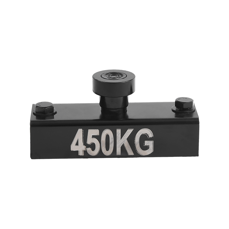
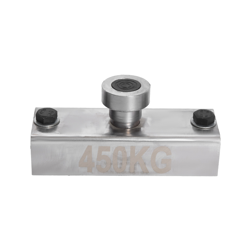
Proces odlievania za mokra využíva jednotlivé oceľové formy alebo paletové systémy, na ktorých sa montujú debniace prvky. tu debniace magnety — známe aj ako magnetické kotvy debnenia alebo magnetické boxy — zohrávajú ústrednú a veľmi viditeľnú úlohu. Tieto zariadenia sú umiestnené na povrchu oceľovej palety a priťahujú magnetickou silou, aby držali bočné uzávery, uzávery, vložky a výstužné klietky v presnej polohe počas liatia betónu a vibrácií. Prídržné sily sa pohybujú v širokom rozsahu v závislosti od konštrukcie magnetu, pričom bežné jednotky dodávajú 600 kg, 900 kg, 1 200 kg alebo dokonca 2 100 kg prídržnej sily zvolenej na základe hmotnosti a zaťaženia vibráciami, ktorým musí debnenie odolávať.
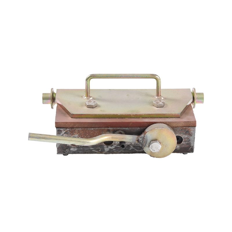
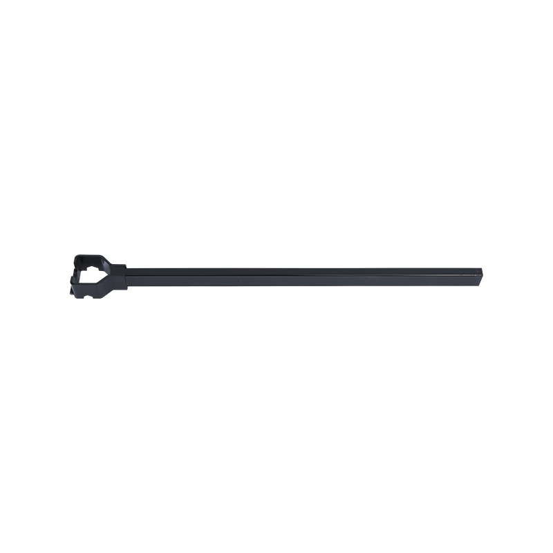
Schopnosť zmeniť polohu magnetov debnenia v priebehu niekoľkých sekúnd – jednoduchým prepnutím aktivačnej páky na uvoľnenie magnetického poľa – dramaticky skracuje čas nastavenia v porovnaní so skrutkovanými alebo zváranými kotvami. Vo vysokovýkonnom prefabrikovanom zariadení na výrobu dutých dosiek na karuseli alebo stacionárnom paletovom systéme sa táto rýchlosť priamo premieta do väčšieho počtu výrobných cyklov za zmenu a nižších mzdových nákladov na jednotku.
Úloha debniacich magnetov pri výrobe dutých dosiek
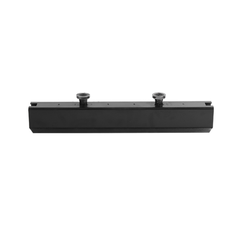
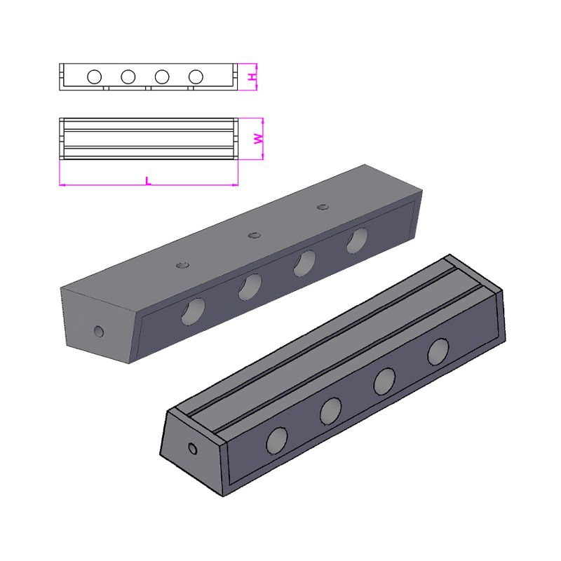
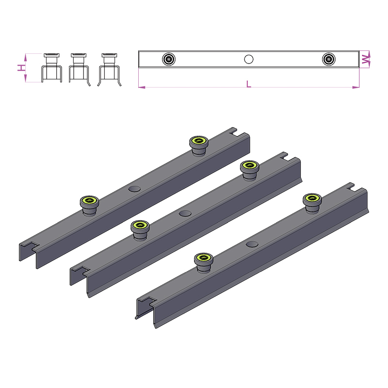
Magnety na uzávierku sú skonštruované upevňovacie zariadenia, ktoré využívajú permanentné neodýmové alebo feritové magnety uzavreté v oceľovom puzdre. Po aktivácii sa magnetický obvod uzavrie cez oceľovú paletu alebo povrch stola, čím sa vytvorí silná prídržná sila. Po deaktivácii – otočením páky, ktorá pohybuje vnútorným magnetom – sa okruh otvorí a jednotku je možné voľne zdvihnúť rukou. Žiadne zvyšky lepidla, žiadny poškodený povrch, nie sú potrebné žiadne špeciálne nástroje.
Pri výrobe dutých betónových dosiek slúžia magnety na debnenie niekoľko špecifických funkcií:
- Zabezpečenie pozdĺžnych bočných tvarov, ktoré definujú šírku dosky a profil hrany
- Držanie koncových uzáverov na mieste, aby sa stanovila dĺžka dosky a vytvorila sa povrchová vrstva
- Upevnenie blokovacích formovačov nad miestami jadra, kde sú potrebné otvory pre rozvody, stĺpy alebo upevňovacie prvky
- Kotviace zaliate vložky, ako sú zdvíhacie slučky, kotviace kanály, závitové objímky a konzoly elektrických vedení
- Stabilizácia výstužných klietok proti posunutiu pri vysokofrekvenčných vibráciách betónu
Vzťah medzi výberom magnetu debnenia a vibráciami betónu je obzvlášť dôležitý. Vibrujúci betón pôsobí na debnenie dynamickými silami, ktoré môžu byť niekoľkonásobkom statickej hmotnosti. Magnet debnenia dimenzovaný na statickú prídržnú silu 1 200 kg môže byť vhodný pre formu s hmotnosťou iba 80 kg, keď sú frekvencie a amplitúdy vibrácií malé, ale ten istý magnet sa môže ukázať ako nedostatočný pri intenzívnych vnútorných vibráciách. Renomovaní výrobcovia zverejňujú spolu so statickými hodnotami aj údaje o držaní podľa vibrácií a špecifikácia samotnej statickej sily je bežnou chybou, ktorá vedie k pohybu formy počas odlievania.
Typy magnetov a ich použitie
| Typ magnetu | Typická prídržná sila | Primárne použitie pri výrobe dosiek | Kľúčová výhoda |
|---|---|---|---|
| Štandardný krabicový magnet | 600 – 1 200 kg | Bočné tvary, koncové dorazy | Cenovo výhodné, široko dostupné |
| Odolný boxový magnet | 1 500 – 2 100 kg | Ťažká oceľová hrana, veľké bloky | Vysoká odolnosť proti vibráciám |
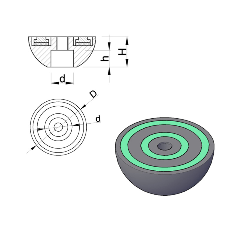
| Vložte magnet (plochý) | 150-400 kg | Kotviace kanály, zdvíhacie zásuvky | Nízky profil, hodí sa pod vložky |
| Magnetický držiak skosenia | N/A (pozičné) | Pásy na skosenie hrán na stropnej doske | Konzistentné detaily okrajov |
| Magnetický rohový uhol | Variabilné | 90° križovatky, blokovacie rohy | Eliminuje únik škárovacej hmoty v rohoch |
Konštrukčné vlastnosti betónových dosiek s dutinkovým jadrom
Konštrukčné správanie betónovej dosky s dutým jadrom sa riadi úrovňou jej predpätia, triedou betónu, geometriou jadra a pomerom rozpätia k hĺbke. Štandardné jednotky s dutým jadrom sa vyrábajú v hĺbkach od 150 mm až 500 mm so šírkami typicky 1200 mm. V praxi sú bežné rozpätia 6 m až 18 m, pričom dobre navrhnuté hlboké jednotky dosahujú 20 m alebo viac pri kontrolovaných podmienkach zaťaženia.
Predpätie sa aplikuje prostredníctvom predpätých vysokopevnostných oceľových laniek – zvyčajne s medzou klzu 1 570 MPa alebo 1 860 MPa – ukotvených k oporám lejárskeho lôžka pred uložením betónu. Po dosiahnutí požadovanej pevnosti pri prenose betónu (zvyčajne 25–30 MPa kocka) sa pramene odrežú alebo uvoľnia a predpínacia sila sa prenesie na betónovú časť väzbou. To zavádza efekt preklenutia (horný oblúk), ktorý čiastočne kompenzuje priehyb pri prevádzkovom zaťažení.
Typický výkon v rozsahu zaťaženia
| Hĺbka dosky (mm) | Rozpätie 6 m (kN/m²) | Rozpätie 9 m (kN/m²) | Rozpätie 12 m (kN/m²) | Rozpätie 15 m (kN/m²) |
|---|---|---|---|---|
| 150 | ~10 | ~3.5 | — | — |
| 200 | >15 | ~7 | ~3 | — |
| 265 | >15 | ~11 | ~6 | ~2.5 |
| 320 | >15 | >15 | ~10 | ~5 |
| 400 | >15 | >15 | >15 | ~10 |
Tieto obrázky ilustrujú, prečo sú duté dosky špecifikované pre stredné až dlhé rozpätia v kancelárskych budovách a parkoviskách, kde je štandardné zaťaženie 2,5–5,0 kN/m² a rozpony 9–14 m sú ekonomicky atraktívne. Predpätie v mnohých prípadoch eliminuje potrebu sekundárnych oceľových nosníkov, čím sa zníži konštrukčná hĺbka podlahovej zóny a ušetrí sa významná výška – často 300–500 mm na poschodie – počas životnosti viacpodlažného projektu.
Požiarna odolnosť
Dutinkové betónové dosky ponúkajú vlastnú požiarnu odolnosť prostredníctvom tepelnej hmoty betónu a hĺbky krytia predpínacích prameňov. Typicky dosahuje 200 mm doska s 35 mm pokrytím ťažiska prameňa REI 120 (dvojhodinová požiarna odolnosť konštrukcie) pri štandardnej požiarnej expozícii. Hlbšie jednotky s väčším krytím ľahko dosahujú REI 180 alebo REI 240, čím spĺňajú najnáročnejšie požiadavky na obsadenosť bez dodatočnej protipožiarnej ochrany. Toto je hlavná výhoda v porovnaní s oceľovými alebo drevenými alternatívami, ktoré na dosiahnutie ekvivalentných hodnôt vyžadujú napučiavajúce nátery, sprinklerové systémy alebo kryty.
Systémy debnenia a magnetické upevnenie v závode na výrobu prefabrikátov
Kvalita betónovej dosky s dutinkovým jadrom je neoddeliteľná od kvality systému debnenia použitého na jej výrobu. Či už sa v závode používa stacionárny paletový systém, rotačný karusel alebo lejacie lôžka s dlhými linkami, presnosť nastavenia a zaistenia debnenia určuje presnosť rozmerov, povrchovú úpravu a konzistenciu hotových prvkov.
Paletové karuselové systémy
V modernom paletovom karuseli sa oceľové palety pohybujú cez pevnú sekvenciu staníc: čistenie, nastavenie formy, umiestnenie výstuže, odlievanie betónu, vibrácie, vytvrdzovanie, vyberanie z formy a transport prvkov. Celý cyklus zvyčajne trvá 24 hodín, pričom v obehu je súčasne viacero paliet. Na stanovišti formy operátori umiestňujú bočné formy a vložky pomocou debniace magnety podľa CNC generovaného alebo výkresového rozloženia pre každý prvok. Pretože povrch palety je presne brúsený oceľový plech, magnety dosahujú konzistentný kontakt a prídržnú silu po celej ploche.
Zvýšenie účinnosti pri upevňovaní magnetického debnenia v karuselovom systéme je značné. Štúdie európskych výrobcov prefabrikátov neustále uvádzajú 30-50% skrátenie času tuhnutia formy v porovnaní so skrutkovými alebo zváranými kotevnými systémami. V závode, ktorý vyrába 80 – 120 paliet denne, to znamená hodiny ušetrenej práce za zmenu a merateľné zníženie výrobných nákladov na meter štvorcový dosky.
Lôžka na odlievanie s dlhými líniami pre extrudované duté jadro
Pri dlhej extrúzii plní primárnu funkciu debnenia samotné lejacie lôžko — plochý, hladký oceľový alebo polymérom potiahnutý povrch, po ktorom sa extrudér pohybuje. Debniace magnety a súvisiace magnetické kotviace systémy sa však používajú na uchytenie:
- Deflektory a deviátory prameňov, ktoré profilujú trajektóriu predpätia
- Pozdĺžne bočné koľajnice, ktoré definujú šírku dosky pred spustením extrudéra
- Formovače blokovania jadra, ktoré vytvárajú otvory pre prestupy služieb na špecifikovaných miestach
- Výstužné prúty alebo sieťovina pridaná do mokrého betónového povrchu pre kompozitné spoje vrchnej vrstvy
Neinvazívny charakter magnetického upevnenia sa cení najmä na lôžkach s dlhými vlascami, kde povrch musí zostať nepoškodený počas tisícok výrobných cyklov. Akékoľvek povrchové ryhy alebo jamy spôsobené vŕtaním alebo zváraním sa stávajú zdrojom úniku a lepenia malty, čím sa zvyšuje sila odformovania a povrchové chyby na dokončenom podhľade dosky.
Výber správneho magnetu uzávierky
Výber správneho magnetu debnenia pre konkrétnu aplikáciu výroby dutých dosiek vyžaduje zváženie niekoľkých faktorov, ktoré presahujú jednoduché prispôsobenie prídržnej sily na hmotnosť formy:
- Hrúbka palety alebo stola: Magnety sú navrhnuté na prácu so špecifickými hrúbkami ocele (zvyčajne 10–25 mm). Príliš tenký a magnetický obvod je neúplný; príliš hrubé a prídržná sila výrazne klesá.
- Metóda vibrácií betónu: Vonkajšie stolové vibrátory vytvárajú vyššie dynamické sily ako vnútorné ihlové vibrátory. Magnety v externe vibrovaných systémoch potrebujú vyššie menovité prídržné sily – často 1,5 až 2-násobok staticky vypočítanej požiadavky.
- Tlak sladkej vody a betónová hlava: Vo vysokých prvkoch alebo tam, kde sa betón ukladá rýchlo, môže hydraulický tlak na debny prekročiť jednoduché výpočty hmotnosti. Magnet musí odolávať vertikálnej zdvíhacej sile aj bočnému tlaku.
- Materiál formy a geometria: Oceľové formy prenášajú magnetickú silu priamo; hliníkové alebo plastové formy vyžadujú oceľové základné dosky, ktoré pôsobia ako sprostredkovatelia medzi magnetom a neferomagnetickým materiálom formy.
- Operačné prostredie: Zariadenia s mostovými žeriavmi, elektromotormi alebo inými elektromagnetickými zdrojmi môžu vyžadovať magnety s tieneným krytom, aby sa zabránilo neúmyselnej deaktivácii alebo rušeniu.
Poprední výrobcovia – vrátane Ratec, Halfen, Sommer a ďalších – ponúkajú inžiniersku podporu pre výber magnetov a zverejňujú podrobné technické listy so statickou prídržnou silou, silou testovanou na vibrácie, rozsahom prevádzkových teplôt a životnosťou cyklu (zvyčajne dimenzované na 500 000 až 1 000 000 aktivačných cyklov predtým, ako vnútorné komponenty vyžadujú kontrolu).
Preprava, manipulácia a montáž dutých dosiek
Po odliatí, vytvrdnutí a narezaní na dĺžku sa betónové dosky s dutým jadrom musia zdvíhať, prepravovať a inštalovať opatrne. Predpätý úsek je optimalizovaný na pozitívny ohyb v smere rozpätia; nesprávna manipulácia, ktorá spôsobuje negatívne ohyby alebo priečne zaťaženie, môže spôsobiť praskliny na predkomprimovanom (podhľadovom) povrchu – poškodenie, ktoré je ťažké zistiť a môže ohroziť výkon konštrukcie.
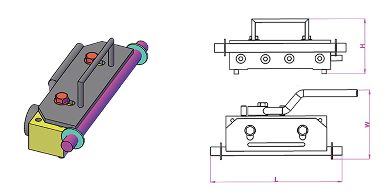
Požiadavky na zdvíhanie a prepravu
Dutinkové dosky by sa mali zdvíhať pomocou účelovo navrhnutých svoriek alebo usporiadaní nosníkov a rozperov, ktoré pôsobia zaťaženie v bodoch v rámci projektovanej zdvíhacej zóny – zvyčajne nie viac ako L/5 z každého konca, kde L je dĺžka dosky. Pre dosky nad 10 m je štandardnou praxou na riadenie ohybových momentov trojbodový alebo štvorbodový zdvih pomocou rozperného nosníka.
Na mieste sa dosky inštalujú pomocou žeriava priamo na nosné trámy, steny alebo konzoly. Dĺžka ložiska na každom konci musí spĺňať minimálne požiadavky – zvyčajne 75 mm na oceľové alebo prefabrikované betónové podpery a 100 mm na murivo alebo betón na mieste — aby sa zabezpečil primeraný prenos zaťaženia a zabránilo sa odlupovaniu konca pri prevádzkovom zaťažení. Neoprénové alebo maltové ložiskové podložky sa používajú na rozloženie kontaktného napätia a prispôsobenie rozmerovým toleranciám.
Injektáž pozdĺžnych škár
Priľahlé duté dosky v podlahe sú spojené injektážou pozdĺžnych škár medzi jednotkami. Škárovacia hmota – zvyčajne zmes portlandského cementu s nízkym pomerom vody a cementu – vyplní kužeľový alebo drážkovaný spoj a po vytvrdnutí prenáša horizontálny šmyk medzi jednotkami, čo umožňuje podlahe pôsobiť ako membrána. Pri seizmickom dizajne je toto pôsobenie membrány rozhodujúce pre rozloženie bočných síl do vertikálneho konštrukčného systému. Injektážna zálievka je často vystužená pozdĺžnymi spojovacími tyčami umiestnenými v otvorených jadrách na okrajoch a zaliatymi, čím sa poskytuje súvislé vystuženie cez spoj.
Presnosť pozdĺžneho spoja závisí čiastočne od toho, ako presne bol tvar hrany držaný počas odlievania - ďalší bod, kde debniace magnety a súvisiace magnetické upevňovacie príslušenstvo priamo ovplyvňuje kvalitu inštalovanej podlahy. Forma, ktorá sa počas odlievania posunula dokonca o 3–5 mm, môže vytvoriť geometriu spoja, ktorú je ťažké úplne škárovať, pričom zanecháva dutiny, ktoré znižujú prenos šmyku a odolnosť voči vode.
Betónové polevy na mieste
Mnohé z dutých doskových podláh sú špecifikované so štrukturálnou betónovou povrchovou vrstvou na mieste, typicky s hrúbkou 50 – 75 mm, naliatou na prefabrikované jednotky po inštalácii. Táto poleva slúži na viaceré účely:
- Vyrovnáva povrch podlahy a vyrovnáva rozdiel medzi priľahlými doskami
- Vytvára robustnú membránu spojením všetkých jednotiek súvislou vystuženou doskou
- Umožňuje integráciu podlahového poteru, podlahového vykurovania alebo inštalačných prác v rámci hĺbky obkladu
- Pri kompozitnom návrhu zvyšuje konštrukčnú hĺbku a nosnosť podlahy
Vrchný povrch dutých dosiek vyrobených extrúziou je zámerne ponechaný drsný – proces extrúzie zanecháva zvlnenú alebo pruhovanú textúru, ktorá poskytuje mechanické spojenie vrchnej vrstvy. Jednotky odlievané za mokra vyžadujú prípravu povrchu (zvyčajne otryskanie alebo mechanickú vertikutáciu), aby sa dosiahla ekvivalentná pevnosť spoja, čo zvyšuje výrobný krok a súvisiace náklady.
Udržateľnosť a materiálová efektívnosť dutých betónových dosiek
Stavebný priemysel čelí rastúcemu tlaku na znižovanie spotreby uhlíka a materiálov. Dutinkové betónové dosky sa priaznivo porovnávajú s alternatívnymi podlahovými systémami v niekoľkých metrikách trvalej udržateľnosti, najmä ak sa berie do úvahy celý životný cyklus.
Znížený objem betónu a ocele
Odstránením betónu z jadrovej zóny – kde len málo prispieva k odolnosti v ohybe – sa využíva výroba dutých jadier O 30–45 % menej betónu na meter štvorcový ako ekvivalentná pevná doska pri rovnakom rozpätí a nosnosti. Použitie vysokopevnostnej predpínacej ocele (1 860 MPa) namiesto bežnej výstuže z mäkkej ocele (500 MPa) znamená, že aj celková hmotnosť ocele na jednotku plochy je výrazne znížená: dutá doska môže spotrebovať len 2–4 kg/m² predpínacieho pásu v porovnaní s 8–15 kg/m² výstužnej dosky navrhnutej pre konvenčnú vystuženú dosku s rovnakou výkonnosťou.
Táto redukcia materiálu priamo znižuje obsah uhlíka v štruktúre podlahy. Priemyselné údaje naznačujú, že typická doska s dutým jadrom s priemerom 265 mm má zabudovaný uhlík približne 100 – 130 kg CO₂e/m² v porovnaní so 160 – 200 kg CO₂e/m² pre pevnú plochú dosku in situ s podobnou konštrukčnou schopnosťou.
Továrenská výroba a znižovanie odpadu
Továrenská výroba v kontrolovaných podmienkach minimalizuje plytvanie materiálom z nadmerného objednávania, rozliatia a prepracovania. Betónový odpad v dobre riadenom závode na výrobu prefabrikátov zvyčajne tvorí 1 – 3 % objemu výroby v porovnaní s 5 – 10 % alebo viac na bežnom mieste na mieste. Použitie debniacich magnetov a opätovne použiteľných oceľových foriem ďalej znižuje odpad z debnenia; vysokokvalitná oceľová forma používaná s magnetickým ukotvením môže byť znovu použitá pre tisíce výrobných cyklov, zatiaľ čo drevené debnenie na mieste sa zvyčajne vyradí po niekoľkých použitiach.
Úvahy o konci životnosti
Na konci životnosti môžu byť betónové dosky s dutým jadrom rozbité a recyklované ako kamenivo pre cestný podklad, výplňový materiál alebo – v pokročilejších recyklačných tokoch – opätovne spracované na betónové kamenivo. Predpínacie vlákno môže byť regenerované a recyklované ako oceľový odpad. Ani jeden proces nie je dokonalý a pri demolácii a preprave sa stratí určité množstvo obsiahnutého uhlíka, ale relatívna jednoduchosť zloženia materiálu (betón plus oceľ) robí dosky s dutým jadrom jednoduchšie na recykláciu ako kompozitné systémy zahŕňajúce viacnásobne spájané materiály.
Bežné aplikácie a príklady projektov
Dutinkové betónové dosky sú špecifikované pre širokú škálu typov budov a infraštruktúrnych aplikácií. Ich všestrannosť pramení zo širokého rozsahu dostupných hĺbok, schopnosti prispôsobiť sa inštalačným prestupom a zaliatym kotveniam (presne umiestnené pomocou magnetických kotiev debnenia počas výroby) a ich kompatibilite s rôznymi nosnými konštrukciami.
Viacposchodové obytné budovy
V bytovej výstavbe sú 200–265 mm duté dosky s rozpätím 5–9 m medzi nosnými stenami alebo nosníkmi štandardnou špecifikáciou v Holandsku, Škandinávii, strednej Európe a Spojenom kráľovstve. 15-poschodový bytový dom s prefabrikovanými dutými podlahami môže byť vodotesný za 8–12 týždňov od prízemia, v porovnaní s 20–30 týždňami pre ekvivalentnú betónovú konštrukciu na mieste. Pravidelný pôdorys obytných budov obzvlášť dobre vyhovuje jednotnej šírke a štandardnému rozpätiu dutých jednotiek.
Obchodné kancelárske budovy
Administratívne budovy vyžadujú dlhšie rozpätia pre flexibilitu otvoreného plánu, zvyčajne 9–14 m. Hlboké duté dosky (320–400 mm) s vysokými úrovňami predpätia sú navrhnuté tak, aby prenášali užité zaťaženie 3,5–5,0 kN/m² v týchto rozpätiach bez sekundárnych nosníkov. Odkrytý podhľad dutých dosiek – inherentne plochý a hladký z procesu vytláčania alebo mokrého odlievania – je stále viac viditeľný ako konštrukčný prvok, čím sa vyhýbajú nákladom na zavesené stropy a získavajú sa výhody tepelnej hmoty, ktoré znižujú špičkové chladiace zaťaženie o 15–25 % v dobre navrhnutých prirodzene vetraných budovách alebo budovách so zmiešaným režimom.
Parkoviská
Viacpodlažné parkoviská sú jedným z najnáročnejších prostredí pre prefabrikovaný betón: bežné sú rozpätia 15 – 18 m, sústredené zaťaženie kolies môže dosiahnuť 30 – 60 kN na nápravu a konštrukcia je vystavená rozmrazovacím soliam, cyklom zmrazovania a rozmrazovania a vlhkosti. Duté jadrové dosky v aplikáciách na parkoviskách sú typicky Hĺbka 400-500 mm , vyrobené s vysokými triedami betónu (C50/60 alebo viac) a nízkymi pomermi voda-cement na maximalizáciu trvanlivosti. Tenké pásy medzi jadrami si vyžadujú starostlivý návrh betónovej zmesi – nízku maximálnu veľkosť kameniva, primeranú spracovateľnosť – a presné zhutnenie, ktoré je uľahčené kontrolovaným výrobným prostredím a systémami kontroly kvality závodu na výrobu prefabrikátov.
Priemyselné a skladové budovy
Sklady, distribučné centrá a výrobné zariadenia používajú duté dosky v medziposchodiach, vyvýšené nakladacie rampy a podlahy s podperou na hromadách. V týchto aplikáciách možnosť predinštalovať zaliate zdvíhacie zásuvky, kotviace kanály pre regálové systémy a elektrické vedenie – všetko umiestnené pomocou magnetických kotiev debnenia počas výroby – výrazne znižuje náklady na upevnenie na mieste a riziko programu.
Kontrola kvality a normy pre betónové dosky s dutinkovým jadrom
Dutinkové betónové dosky vyrobené v Európe musia spĺňať EN 1168:2005 A3:2011 — harmonizovaná výrobková norma pre prefabrikované betónové duté dosky. Táto norma špecifikuje výkonnostné požiadavky na konštrukčnú odolnosť, požiarnu odolnosť, nebezpečné látky, rozmerové tolerancie a akustické vlastnosti spolu s požiadavkami na vnútropodnikovú kontrolu výroby, skúšanie a označenie CE.
Kľúčové rozmerové tolerancie podľa EN 1168 zahŕňajú:
- Dĺžka: ±20 mm pre dosky do 6 m; ±0,3 % dĺžky pre dosky nad 6 m
- Šírka: ±5 mm
- Hĺbka: ±5 mm
- Priamosť: ≤L/600, maximálne 20 mm
- Štvorhrannosť koncov: ≤10 mm
- Prevýšenie: 15/−5 mm pre dosky do 12 m
Dosiahnutie týchto tolerancií dôsledne závisí od kvality celého výrobného reťazca – od návrhu zmesi a dávkovania betónu, cez presnosť napínania pásu až po nastavenie debnenia a kontrolu po odliatí. Použitie debniacich magnetov a súvisiacich magnetických polohovacích systémov prispieva k rozmerovej presnosti tým, že eliminuje polohový posun, ku ktorému dochádza pri konvenčných skrutkových formách pri vibráciách, a umožňuje rýchle a presné premiestnenie pri zmene nastavenia.
Okrem rozmerových tolerancií vyžaduje EN 1168 a podporné konštrukčné normy Eurocode (EN 1992-1-1, EN 1992-1-2) podrobné konštrukčné overenie týkajúce sa ohybu, šmyku, dierovania, kotvenia na konci a požiarnej odolnosti. Proces navrhovania podlahy s dutým jadrom zahŕňa určenie maximálneho rozpätia pre požadované zaťaženie, výber vhodnej hĺbky dosky a usporiadania prameňov z tabuliek zaťaženia výrobcu, kontrolu dĺžky ložísk, overenie pôsobenia membrány injektovanej podlahy a koordináciu servisných prestupov so statikom.
Porovnanie dutých dosiek s alternatívnymi podlahovými systémami
Výber medzi betónovými doskami s dutým jadrom a konkurenčnými podlahovými systémami si vyžaduje zváženie konštrukčného výkonu, rýchlosti programu, nákladov, udržateľnosti a obmedzení na mieste. Žiadny jednotlivý systém nezvíťazí pri každom kritériu, ale duté dosky majú jasné výhody v špecifických scenároch.
| Kritérium | Dutá doska | Plochá doska na mieste | Kompozitná oceľová paluba | Pevná prefabrikovaná doska |
|---|---|---|---|---|
| Typický rozsah rozpätia | 6-20 m | 5-12 m | 3–9 m (palubné) nosníky | 3-7 m |
| Hmotnosť (sama) | Nízka – Stredná | Vysoká | Nízka – Stredná | Vysoká |
| Rýchlosť inštalácie | Veľmi rýchlo | Pomalé (debnenie, ošetrenie) | Rýchlo | Rýchlo |
| Požiarna odolnosť (žiadna dodatočná ochrana) | REI 60–240 | REI 60–180 | Typicky REI 30–60 | REI 60–180 |
| Materiálová efektívnosť | Vysoká | Nízka | Stredná | Nízka |
| Akustický výkon | Dobré (s poterom) | Dobre | Spravodlivé (vyžaduje liečbu) | Dobre |
| Integrácia služieb | Stredná (cores usable) | Vysoká (flexible) | Vysoká | Nízka |
Samotné jadrá ponúkajú užitočnú výhodu pre technické vybavenie budov: v niektorých konštrukčných prístupoch sa pozdĺžne dutiny používajú ako vzduchové kanály na vykurovanie, chladenie alebo vetranie, pričom upravený vzduch prechádza cez dosku tak, aby obsluhoval obývaný priestor a využíval tepelnú hmotu betónu na temperovanie. Tento prístup tepelne aktivovaného systému budov (TABS) bol implementovaný v mnohých kancelárskych projektoch v strednej Európe s merateľným znížením špičkových požiadaviek na chladenie až do 30 – 40 % v porovnaní s konvenčnými systémami na strane vzduchu.
Praktické úvahy pre špecifikátorov a dodávateľov
Špecifikácia alebo obstaranie betónových dosiek s dutým jadrom si vyžaduje spoluprácu s výrobcom na začiatku procesu návrhu. Na rozdiel od betónu na mieste, ktorý je možné upraviť na mieste, sú dosky z dutých jadier rozmerovo fixované v továrni. Zmeny po výrobe — výrezy, dodatočné upevnenie, úpravy výstuže — sú technicky možné, ale nákladné a časovo náročné. Získanie toku informácií priamo vo fáze návrhu je rozhodujúce.
Informácie požadované vo fáze návrhu
- Konštrukčné zaťaženie: vlastná hmotnosť, navrstvené mŕtve (poter, priečky, povrchové úpravy), uložené (kategória obsadenosti) a akékoľvek sústredené zaťaženie z upevnenia závodu, skladu alebo obkladu
- Jasné rozpätie a podmienky uloženia na každej podpere vrátane akýchkoľvek neparalelných podpier alebo šikmej geometrie
- Trieda požiarnej odolnosti požadovaná pre podlahovú zónu
- Umiestnenie, veľkosť a rámovanie všetkých prestupov, vrátane MEP objímok, drenážnych rúr, konštrukčných stĺpov prechádzajúcich podlahou a otvorov výťahovej šachty
- Potrebné zaliate upevňovacie prvky: kotevné kanály, zdvíhacie hrdlá, upevňovacie skrutky, čapy potrubia – všetky sa umiestňujú pomocou magnetických kotiev debnenia a zalievajú sa počas výroby
- Požiadavky na akustický výkon, najmä v prípade rezidenčných projektov alebo projektov so zmiešaným využitím, kde náraz a zvuk prenášaný vzduchom musia spĺňať regulačné normy
- Hranice priehybu a očakávané vyklenutie, najmä tam, kde budú krehké povrchové úpravy (dlaždice, terazzo) aplikované priamo na povrch dosky
Koordinácia miesta inštalácie
Inštalácia dutých dosiek na mieste si vyžaduje koordináciu kapacity žeriavu, prístupových trás, dočasného podopretia (ak to vyžaduje konštrukčný návrh) a postupnosti injektáže, zálievok a detailov konštrukčného spojenia. Kapacita žeriavu je často kritickým obmedzením : 400 mm dutá doska s dĺžkou 12 m a šírkou 1,2 m váži približne 5 000 – 5 500 kg. Na obmedzenom mestskom mieste, kde dosah žeriavu znižuje nosnosť, si to môže vyžadovať zníženie dĺžky dosky alebo špecifikáciu ľahšej jednotky – rozhodnutie, ktoré sa kaskádovito vracia k dizajnu rozpätia, zaťaženia a nosnej konštrukcie.
Škárovanie škár by malo presne zodpovedať špecifikácii výrobcu. Použitie škárovacej hmoty, ktorá je príliš vlhká, vytvára porézny, slabý spoj náchylný na praskanie; príliš suchý a nemusí úplne vyplniť profil kužeľovej škáry, pričom zanecháva dutiny. Škárovanie škár na veľkých podlahových plochách by sa malo plánovať ako nepretržitá operácia s primeraným personálom a kapacitou miešania, aby sa predišlo studeným škáram v rámci jednej škáry.
Kontroly po inštalácii
Po inštalácii a škárovaní by sa mala dokončená dutinová podlaha skontrolovať na:
- Diferenciálny sklon medzi susednými jednotkami – prípustný v rozmedzí ±5 mm bez prekrytia; ak je väčšia, môže byť potrebná ďalšia hĺbka poteru na dosiahnutie rovného povrchu
- Úplnosť škárovacej hmoty vo všetkých pozdĺžnych a priečnych škárach
- Adekvátnosť koncového ložiska na všetkých podperách
- Stav zaliatych vložiek – všetky poškodené alebo nesprávne umiestnené vložky by mali byť nahlásené a opravené pred aplikáciou vrchnej vrstvy alebo povrchovej úpravy
- Absencia poškodenia pri manipulácii: praskanie na koncoch dosiek, odlupovanie v ložiskových oblastiach alebo pozdĺžne praskanie v stojinách, čo môže naznačovať poškodenie pri preprave alebo montáži
Inovácie v technológii dutých dosiek a v systémoch magnetického debnenia
Priemysel prefabrikovaného betónu pokračuje vo vývoji výrobkov z dutých dosiek a výrobných systémov používaných na ich výrobu. Pre tých, ktorí sa rozhodujú o dlhodobých investíciách do infraštruktúry, stojí za zmienku niekoľko oblastí aktívneho rozvoja.
Mimoriadne vysokovýkonný betón vo výrobe dutých jadier
Výskum ultra-vysokohodnotného betónu (UHPC) pre aplikácie dutých jadier prebieha v niekoľkých európskych a ázijských výskumných programoch. Zmesi UHPC s pevnosťou v tlaku 150–200 MPa umožňujú ďalšie znižovanie hrúbky pásu, čím sa znižuje vlastná hmotnosť pri zachovaní kapacity v šmyku. Výrobnou výzvou je, že UHPC nie je kompatibilný so štandardným vytlačovacím zariadením – vystuženie vláknami a viskozita zmesi si vyžadujú modifikované metódy odlievania – a úloha debniace magnety and precision magnetic formwork systems pri umiestňovaní tenších foriem s vyššou presnosťou sa stáva ešte kritickejším.
Automatizácia a robotika v nastavení debnenia
Niekoľko výrobcov prefabrikovaných zariadení teraz ponúka robotické systémy na nastavenie debnenia, ktoré čítajú rozloženie prvkov z BIM modelu a automaticky umiestňujú bočné debnenia, koncové dorazy a vložky na povrch palety. Tieto systémy zvyčajne využívajú portálové roboty s kamerovým systémom na vyberanie a umiestňovanie komponentov debnenia debniace magnety ako konečný upevňovací mechanizmus – robot umiestni formu a aktivuje sa magnetická kotva, ktorá ju zablokuje na mieste. Prví používatelia týchto systémov uvádzajú presnosť nastavenia formy ±1–2 mm a časy cyklov výrazne pod úrovňou manuálneho nastavenia, s konzistentnou kvalitou a zníženou únavou operátora.
Digitálna integrácia a inteligentná výroba
Moderné závody na výrobu prefabrikátov čoraz viac integrujú technológiu digitálneho dvojčaťa – virtuálny model výroby v reálnom čase – so systémami kontroly kvality, riadením zásob a logistikou. Každému prvku je v mieste výroby priradený jedinečný QR kód alebo RFID tag, ktorý spája jeho digitálny záznam s konkrétnou šaržou betónu, šaržou prameňa, polohou vložiek upevnenou magnetom a výsledkami kontroly rozmerov. Túto sledovateľnosť stále viac požadujú hlavní dodávatelia a klienti pri zložitých projektoch, kde sa vyžaduje štrukturálna zodpovednosť počas projektovanej životnosti budovy 50 – 100 rokov.
Presnosť upevnenia magnetického debnenia – kombinovaná s laserovými kontrolami kvality hotového prvku pred expedíciou – tvorí súčasť tohto digitálneho reťazca kvality. Doska, ktorá prejde všetkými rozmerovými kontrolami, záznamami o pevnosti betónu a vizuálnou kontrolou, je odoslaná s úplným záznamom o výrobe, ktorý je prístupný pomocou QR skenovania na mieste, čo umožňuje stavebnému inžinierovi alebo vlastníkovi budovy overiť súlad bez toho, aby sa spoliehal iba na papierové certifikáty.